What I Want to Achieve
I’m a guy who enjoys the simple pleasures: a giant computer monitor and some cool atmospheric lights that react to the videos playing on it.
Sure, I could’ve bought something like that online, but this product was unavailable on Amazon India. With the exchange rate and customs fees, it would’ve been prohibitively expensive and a huge hassle. So, I decided to roll up my sleeves and make one myself.
Here’s what the retail product looks like,
Naturally, I spent the entire weekend obsessing over how to make this happen, all while keeping it as cost-effective as possible. And here’s what my DIY version looks like:
Here’s what my version looks like.
The Basic Game Plan
So roughly I need to do the following:
- Capture a screenshot of what’s playing
- Analyse the image and translate it into corresponding colors
- Send the color data to a microcontroller that controls an LED strip
This process needs to be repeated as often as possible to provide a seamless experience. .
What’s required
Now, let’s dive into what’s needed to make this plan a reality. I’ve dabbled in building my own mechanical keyboard from scratch, which gave me some experience working with micro-controllers and micropython. After some online sleuthing, I came up with this list:
1. WS2812b Controllable LED Strip
These compact, three-pin LEDs are easy to power and widely used in DIY projects.
2. Xiao Seeed Studio ESP32-C6 Microcontroller
The ESP32 platform offers WiFi6 and Bluetooth connectivity, plenty of GPIO pins, and MicroPython support. The Xiao Seeed Studio’s tiny form factor is ideal for my limited desk space. Plus, it has a USB-C input jack, so it can be powered with a standard phone charger.
3. A way to Decode what’s on the screen
We’ll start small by focusing on a single media player: VLC. VLC has a built-in web API that allows full control, including taking screenshots. We can easily read these screenshots, process them with Python, and send the processed data to the microcontroller via WiFi.
Hardware side of things
This part turned out to be more straightforward than I expected. Aside from some soldering, it was much like putting together a set of Lego blocks.
Step 1. Setup the LED strip

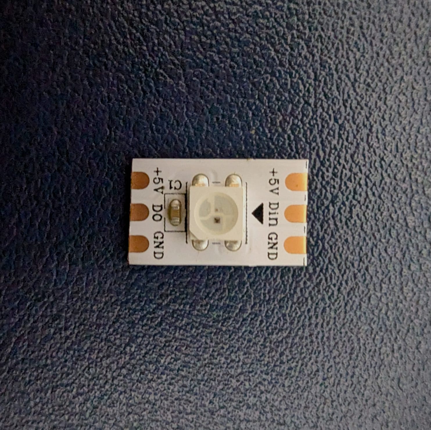
A single LED from the strip
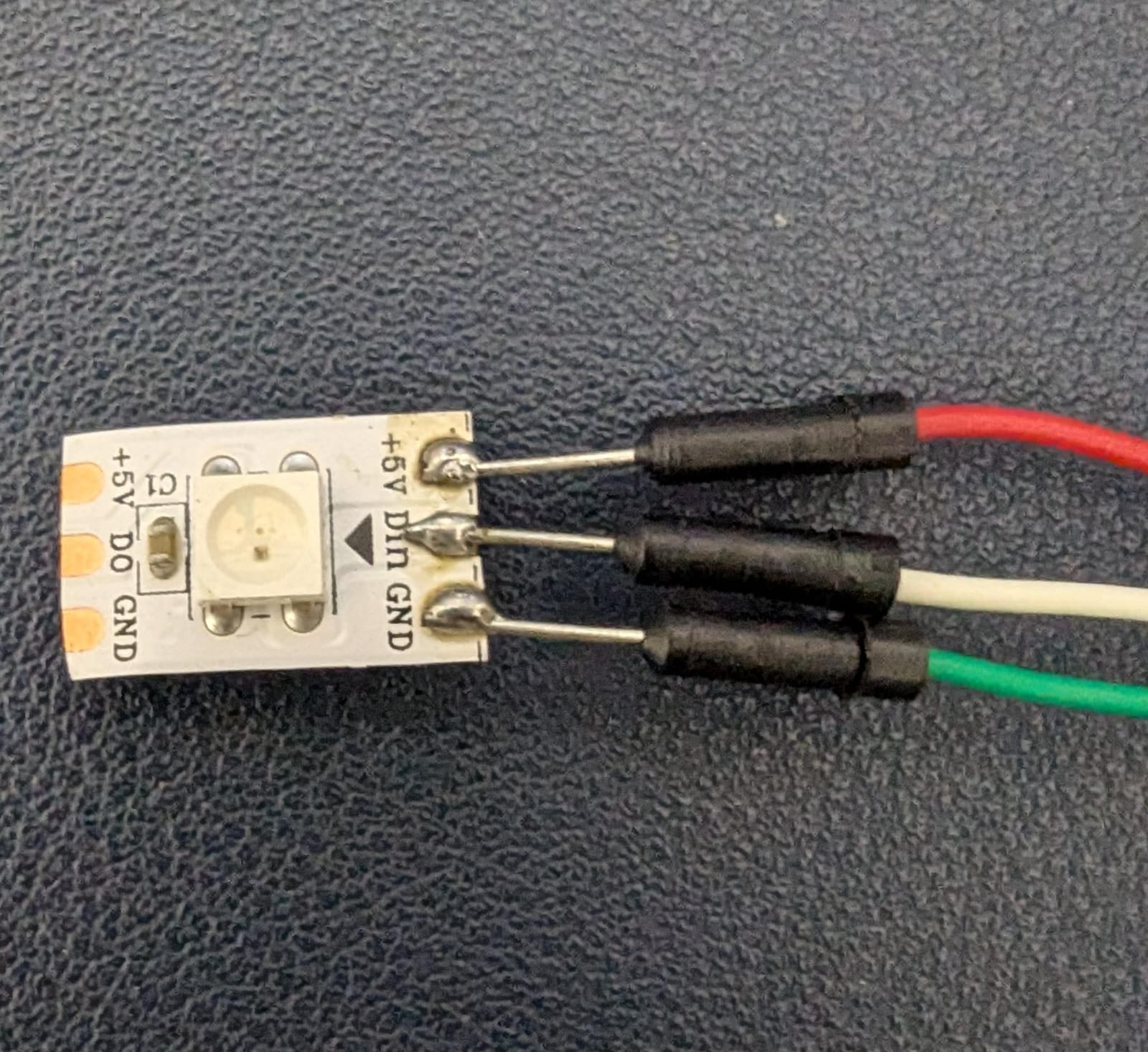
As mentioned earlier, the WS2812b has three pins: a 5V power pin, a Data Input (Din) pin, and a ground (Gnd) pin. I used jumper cables since the microcontroller and LED strip would be assembled on a breadboard.
Here’s what the soldered LED will look like

Soldered LED
Step 2. Attach the LED Strip to the Microcontroller
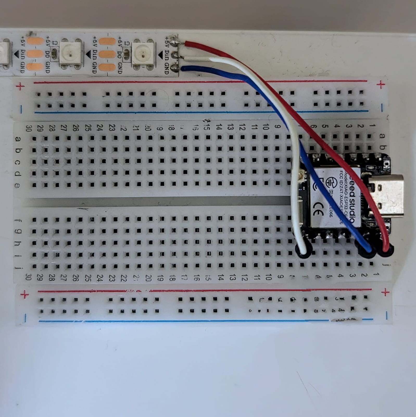
The easy part is connecting everything. All it takes is a couple of jumper cables and a breadboard.
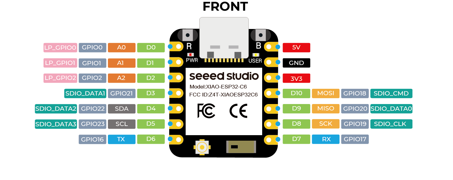
Here’s the pinout for the microcontroller:

Micro-controller Pinout
- The power pin on the LED strip takes a 5V input, which connects to the 5V output pin on the microcontroller.
- The ground pin on the LED strip connects to the ground pin on the microcontroller.
- The “Din” data input pin on the LED strip connects to any general-purpose IO pin (labeled D0 to D10) on the microcontroller. Make sure to note which data pin you use.

Assembled Breadboard
Note: If you’re using a large number of LEDs running at full brightness, consider powering the LED strip with an external power source to avoid frying your microcontroller.
Closing Thoughts
This post covers the hardware setup. In the next one, I’ll dive into the software implementation. Stay tuned!
